The antenna systems or aerial is the final link in the chain that sends out the signal of a radio station so listeners can pick it up and listen. It’s connected to the transmitter by coax and always located at the highest point you can obtain. VHF travels straight to the horizon, so the higher the aerial, the further it travels before disappearing off into space due to the earth’s curvature.
Dipole Antennas
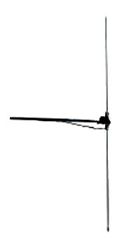
Horizon Radio Antenna Systems started off with Dipoles. The dipole is the simplest type of antenna there is, but has its drawbacks. Its stands out like a sore thumb to anyone with radio experience. It also can give problems in the direction of the signal you wish to send out. Most stations wanted to send out a signal that went 360 degrees covering all areas from the aerial.
The Dipole if not set up 100% correct, it could push most of the signal forward, as the mast it was bolted too, acted as another element, thus parts of the area where not covered very well.
Dipoles where cheap and cheerful, as pop down to the local radio shop in those days, buy a VHF radio aerial, strip it, take off all the extra bits you do not need, tune it to the frequency you broadcast on (cut elements to size). The center of coax goes to the top element of aerial, outer coax to lower element. For vertical polarization keep live at the top. Dipoles are low gain aerials that just about do the job and no more.
Some stations tried to stack these aerials one below each other to get the gain, a good aerial will give, but did not realise that it in most cases it just gave even more problems with direction. Some just did not understand the meaning of the word wavelength?
Horizon Radio Antenna Systems The Slim Jim Antenna
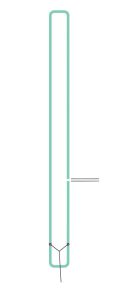
 This little baby really was the aerial to use back then, as so compact. It would not stand out like a sore thumb on a tower block. Horizon made our own from three eights diameter alloy tube. You could make the antenna in a few minutes; again size has to be tuned to the frequency you broadcast on. You need a bend at the top and bottom, so just bend it around a 50mm plastic water pipe. Do it slowly, so no heat is required. The gap on the side is critical.
Connect coax, which you can adjust to get the best SWR, Horizon Radio’s were always unreadable, so low. Tape it to that 3 meter 50mm plastic water pipe, insert a piece of 40m wood up the center of the plastic tube to give stability and the insert into communal aerial mast on tower blocks. Make sure you have the correct space between lower part of aerial and metal mast, just tape it with electrical insulation tape and fit U clamp.
To the average eye from the ground, you would not notice anything unusual up there. Peckham Rye Hill Park had an aerial up there for around a year, no one bothered, even when workforce who were on roof. Stockwell also and that one remained up there for 2+ years after Horizon Radio stopped using it.
Transmission signal was 360 degrees, gain was low but the signal really got out off this aerial. Horizon Radio had listeners in Reading Berkshire, Brighton, Welwyn Garden City, Hoddesdon & Milton Keynes, Hertfordshire along with Southend on Sea. DXers even sent in reports from Europe.
The Slim Jim (the design probably originates with the 2 meter guys). It was a magical little antenna, but there was better to come.
Horizon Radio, That Antenna!
We have no idea what to call this antenna, but boy did it work! Credit has to go to ET  (Ian) as he purchased an antenna book and gave it to Chris, so he could learn all about antenna building. The slim Jim also came out of this book.
The Slim Jim from about 1982 was the Horizon Radio chosen aerial, but after moving to 70 Westow Hill Crystal Palace, our static transmitter site from March 1984. Chris started playing with antenna designs to try and find something that gave performance gain. This antenna idea Chris saw in that book and set about making it. Instead of using alloy 3/8 tube, 13mm copper water pipe was used for the elements. The aerial also required lots of bends, so very easy to do with 90 degree joints that you can buy for the copper water pipe, they came with solder it them, so all you had to do was heat them up to get the fix.
Instead of copying the book, Chris added another section and a matching system so the SWR was low. The big problem was the length, well over 4 meters of 13mm copper water pipe. How do you hold that at the top of a 50ft mast on top of a building up in Crystal Palace in the wind?
The answer was 50mm plastic pipe reinforced with wood inside the pipe, glue and lots of insulation tape, plus guy lines.
Just before the old Slim Jim was taken down and it was running a 400watt transmitter at the time. Pyers Easton took a signal measurement out in Walthamstow Northeast London. After we had put the new antenna up, but only using a 100 watt transmitter as we where in unknown territory at the time.
Pyers came back over the 2 meter radio’s we used to communicate and asked. “Megga what kind of power have you installed now?” He was shocked to learn that was just 100 watts. We put in 160 watts later and left it, as you just did not need any more with that antenna.
Everyone tried to copy that aerial, no one ever did, as no one saw that loop of magic that was also up there hanging on the aerial? In 1985 version 2 of this antenna saw yet another section added to it, the performance gain the aerial gave was magical.


 This little baby really was the aerial to use back then, as so compact. It would not stand out like a sore thumb on a tower block. Horizon made our own from three eights diameter alloy tube. You could make the antenna in a few minutes; again size has to be tuned to the frequency you broadcast on. You need a bend at the top and bottom, so just bend it around a 50mm plastic water pipe. Do it slowly, so no heat is required. The gap on the side is critical.
 (Ian) as he purchased an antenna book and gave it to Chris, so he could learn all about antenna building. The slim Jim also came out of this book.